Biometric-ID-Lock
This is a fingerprint lock that uses an Arduino Microcontroller and 4-Channel Relay Module to unlock a solenoid lock. When the uploaded fingerprint is detected, a red light glows and the solenoid lock unlocks.
| Engineer | School | Area of Interest | Grade |
|---|---|---|---|
| Prathivaradhan Sattiamoorthy | Dublin High School | Mechanical Engineering/Computer Science | 11 |
Final Milestone
Final Milestone Video

For my Final milestone, I added my fingerprint scanner, relay module, solenoid lock, LCD screen, LED with tinned PCB, breadboard and battery. The LCD will help display the proper message accordingly which allows the user to know if the fingerprint is valid or not. The LED is an indicator as to whether the finger has been accepted or not. The relay module is designed as a switch that turns on or off, letting current flow through the solenoid lock or not. The solenoid lock works with the help of electromagnetic energy and often runs on a low DC voltage. The breadboard is helpful as I needed more space for wiring in my Arduino based fingerprint project. I am planning on using my fingerprint scanner, relay module, solenoid lock with LCD screen to display the message accordingly. Also I am planning to use the LED light where it indicates the light when the fingerprint matches. The main components of this milestone include the Arduino microcontroller, Fingerprint Module, relay module, 12 V solenoid lock, LED with tinned PCB and LCD screen. The LCD screen is used to confirm whether the fingerprint is accepted or denied in the system. The LED is an indication whether the fingerprint has been matched or not. To operate the system, I have added proper libraries such as Adafruit Fingerprint, Liquid Crystal_I2C and Wire.h respectively.
Third Milestone
Milestone 3 Video
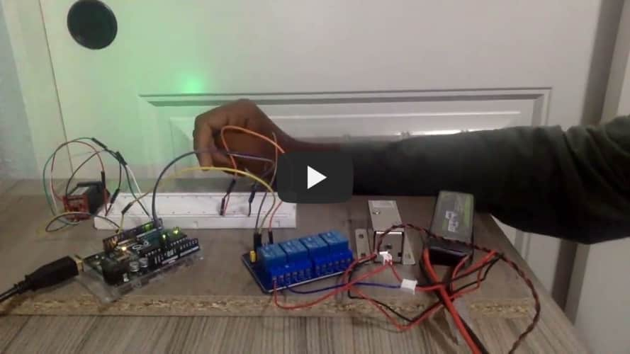
During my third milestone, I added a 12 V solenoid lock, 4-Channel Relay Module, Fingerprint sensor and a battery. The LCD screen is a 16x2 screen that can display characters by being backlit. If the correct fingerprint is scanned, the relay module will turn on or off which allows the current to flow through. The main components of this milestone include the Arduino micro controller, Fingerprint Module, relay module and the 12 V solenoid lock. The relay module is an electrical switch which is operated by an electromagnet. This electromagnet is then activated by a separate low-power signal from a microcontroller. When activated, the electromagnet pulls to either open or close an electrical circuit which makes the Solenoid lock to function. The solenoid lock contains a latch for electrical locking and unlocking. I have connected the battery to GND to the solenoid GND. The battery Power wire and solenoid power are connected the relay module pin.The relay module output is connected to the Arduino pin 13. The GND and VCC of relay module are connected accordingly
Second Milestone
Milestone 2 Video
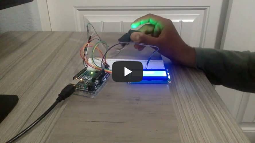
During my second milestone I tested the fingerprint scanner, added an LCD screen to display the message on enrollment and verification of the fingerprint. During this milestone, I added an LCD screen which projects information from the serial print function onto another screen where the information is more visible. The circuit that I created during this milestone works by first placing my finger(s) on the fingerprint sensor. The LCD would state the condition of the fingerprint sensor and display it on the screen. After having my fingerprint stored in the scanner, I found a code online that could be used to activate the LCD screen. Once the fingerprint sensor worked and stored the template, I decided to combine the code of that sensor with the LCD’s code. As the text message is long it got truncated in my LCD screen as its dimension is 16x2, hence decided to scroll the message from right to left when it displays. I used I2C adapter attached to LCD, as chip converts the I2C data from an Arduino into the parallel data required for an LCD display. This has 4 pins to have connected to Arduino. To drive an I2C LCD you must first install a library called LiquidCrystal_I2C and connect the pins as described below.

GND is a ground pin. Connect it to the ground of the Arduino.
VCC supplies power to the module and LCD. Connect it to the Arduino’s 5V output or an external 5V power supply.
SDA is the I2C data pin. Connect it to the Arduino’s I2C data pin.
SCL is the I2C clock pin. Connect it to the Arduino’s I2C clock pin.
First Milestone
Milestone 1 Video

During my first milestone, I built a fingerprint scanner which uploads the fingerprints as templates and verifies to check matching and displays the message in output if its matched or not. This module has FLASH memory for storing fingerprints, and can be used with any microcontroller or system with a TTL serial interface, and can be added to security systems, door locks, time and attendance systems, and so on. Some of the main components include the Arduino microcontroller and fingerprint scanner. The Arduino microcontroller is the center of the circuit as the code is uploaded and the components which sends and recieves data. The easiest way to control the fingerprint sensor module with Arduino is to use the sensor’s Adafruit library. The fingerprint sensor module used in this project has wires of the same color, so it is necessary to distinguish the wire and connect to Arduino board accordingly.

VCC-Red wire - Connect to 5V
RX-Green wire - Pin 2
TX-White wire - Pin 3
GND-Black wire - GND
The easiest way to control the fingerprint sensor module with Arduino is to use the sensor’s Adafruit library. Connect the fingerprint sensor module to the Arduino. To enroll select the template number and scan your finger, rescan again to make sure its gets stored properly. If the finger module couldn’t scan the fingerprint properly due to Image failures or packet receive error it throws the serial output message accordingly. The template number where the fingerprint scan is stored would be given with in the serial output. To verify the fingerprint, run the Fingerprint_verify program to check the fingerprint matches. If the fingerprint matches it gives the template number and gives the output as match found. Sometimes, if your fingers are not placed correctly as they were saved, the sensor can hardly recognize it. Place your finger slowly on the scanner, so that the sensor will work better.
Materials
- Arduino
- 4-Channel Relay Module
- 12V Solenoid Lock
- Fingerprint Scanner
- Tinned Printed Circuit Board
- LCD Display
- Breadboard
- 12V Battery
- Led Light (1)
- Resistor 220 Ohms (1)
- Jumper Wires (Many)
- USB Cable
- Wood Slab
- Tape, zip ties